Manual.ly Logo

Voltcraft VC-13A Bedienungsanleitung

4,0 · 2 Bewertungen

PDF-Handbuch · 12 Seiten

Deutsch

M: QW-35-FL
Seite

/ 12

Loading...
e150e37db53ef651200c1138b7cf35b312de page 5
c) Resistance measurement
Make sure that all the circuit parts, switches and components and other objects to be
measured are disconnected from the voltage and discharged at all times.
Proceed as follows to measure resistances:
• Select the measuring function “Ω” with the rotary switch .
• Connect the black measuring line to the COM socket (5) and the red measuring line to the socket “Ω” (6).
• Touch the two measuring tips to each other and wait until the pointer has stabilised. A value of approx.
0 Ohm must be displayed. In case of a deviation, adjust the pointer with the 0 Ohm calibration control (3)
to 0 Ohm. Always check this when changing the measuring range.
• Read off the measuring value on the scale “Ω”.
• In the “x1k” measurement range, multiply the displayed value by a factor of 1000 to get the measured
value e. g. 5 Ω (display) x 1000 = 5 x 1000 = 5 kΩ (measured value).
• In the “x10” measurement range, multiply the displayed value by a factor of 10 to get the measured value
e. g. 50 Ω (display) x 10 = 50 x 10 = 500 Ω (measured value).
• After completing the measurement, remove the measuring tips from the measuring circuit and switch the
multimeter off (rotary switch position: “OFF”).
d) Direct current measurement
Never exceed the max. permitted input values in the respective measuring ranges.
Current measuring operations are permissible only in circuits up to max. 300 V.
Proceed as follows to measure direct currents up to 250 mA/DC voltages:
• Select the measuring function “mA” with the rotary switch .
• Connect the black measuring line to the COM socket (5) and the red measuring line to the socket “mA” (6).
• Disconnect the object to be measured from the mains.
• Pay attention to the correct polarity (red = + / black = -) and connect the two measuring tips in series with
the measuring object (battery, circuit, etc.).
• In the case of a pole reversal, the needle deects in the negative direction. This could damage the meter
mechanism. Stop the measurement at once and repeat the measurement with the correct polarity.
• Read off the measuring value on the scale “mA”.
• Disconnect the measured object from the mains and remove the measuring tips from the measuring
circuit after the measurement is completed. Switch off the multimeter (rotary switch position “OFF”).
e) Attenuation measurement in dBm
The multimeter enables absolute “dB” measuring in circuits with an impedance of 600 Ohm. Measurements
are made in the “10 V~” range. 0 dB = 1 mW (0.775 V).
Proceed as follows for the measurement:
• With the rotary switch, select the measuring range “10 V~“.
• Connect the black measuring line to the COM socket (5) and the red measuring line to the socket “V” (6).
• Now connect the two measuring probes in parallel to the object to be measured (generator, switch, etc.).
• Read off the measured value on the scale “dB”. Read the voltage on the scale “AC10V”.
• If signals with a direct voltage ratio are to be measured, a capacitor of >0.1nF must be connected in
series to the measuring lines (decoupling).
• After completing the measurement, remove the measuring tips from the measuring circuit and switch the
multimeter off (rotary switch position: “OFF”).
f) Battery test
The multimeter tests 1.5 V or 9 V batteries with a low load. This prevents faulty measurements during
open-circuit operation and gives signicant clues to the battery condition.
"REPLACE" indicates that the battery must be replaced.
"?" indicates that the battery can still be used only for low power consumer loads.
"GOOD" indicates that the battery is OK.
To test the batteries, proceed as follows:
• With the rotary switch select the measuring function “BAT” and the measuring range 1.5 V or 9 V.
• Connect the black measuring line to the COM socket (5) and the red measuring line to the socket “V” (6).
• Pay attention to the correct polarity (red = + / black = -) and connect the two measuring tips to the
battery.
• In the case of a pole reversal, the needle deects in the negative direction. This could damage the meter
mechanism. Stop the measurement at once and repeat the measurement with the correct polarity.
• Read off the measured value on the scale “BAT”.
• After completing the measurement, remove the measuring tips from the measuring circuit and switch the
multimeter off (rotary switch position: “OFF”).
CLEANING AND MAINTENANCE
General information
To ensure the accuracy of the multimeter over an extended period of time, it should be calibrated once a
year.
Information on changing the battery and fuse appears below.
Regularly check the technical safety of the device and the measuring cables, e.g. for
damage to the housing or crimping, etc.
Never operate the meter when it is open. ! RISK OF FATAL INJURY!
EXPLANATION OF SYMBOLS AND SIGNS
Overload, the resistance measuring range was exceeded
Symbol for the built-in battery data
Symbol for the built-in fuse
OFF Switch position OFF
COM Measurement reference potential, - for DC
VmAΩ Measurement input for measurement potential, + for DC
AC Symbol for alternating current
DC Symbol for direct current
V Volt (unit of electric voltage)
mA Milliampere (unit of electric current, exp.-3)
Ω Ohm (unit of electrical resistance)
x10 The resistance value read must be multiplied by 10
x1k The resistance value read must be multiplied by 1000
dB
Decibels, attenuation in the 10 V AC voltage measurement circuit
(0 dB = 1 mW/600 Ohm = 0.775 V)
BAT Battery test
9 V/1.5 V Measurement range for batteries with 9 V or 1.5 V nominal voltage
REPLACE The tested battery must be replaced
? The tested battery should be replaced as soon as possible
GOOD The tested battery can be used
START-UP
Before you can work with the measuring device in the resistance measurement range, you must
rst insert the enclosed battery. Insert the battery as described in the chapter “Cleaning and Mainte-
nance”.
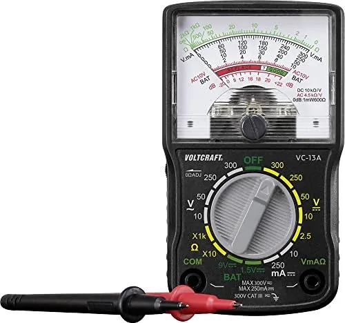
Rotary switch (4)
• The individual measuring functions and ranges can be set using the rotary switch.
• If the rotary switch is set to “OFF”, the measuring device is switched off.
• Always turn the meter off when it is not in use.
• An automatic cut-off does not occur in the resistance range.
WEIGHING
Do not exceed the maximum permitted input values under any circumstances. Never
touch circuits or parts of circuits when they may contain voltages greater than
33 V/ACrms or 70 V/DC! Risk of fatal injury! Before every measurement, check the
meter and the connected measuring leads for damage such as cuts, cracks or pinches.
Remove defective measuring leads immediately and replace them with new measuring
cables. Defective measuring leads must no longer be used. ! Risk of fatal injury!
Before changing the measuring range, the test probes have to be removed from the
measured object.
Always start each measurement with the largest measuring range. Then gradually
change to a smaller one to achieve an exact measured result. The best precision occurs
in the mid-scale range (scale range ca. 70° to 110°).
The measuring results at the rotary switch correspond to the scale end value. For reading, always select
the corresponding value (e.g. scale 10 for the measuring range 10).
a) Zero adjustment
Before each measurement, adjust the zero position with the calibration screw (2) (scale value 0 V). There
must be no measuring signal on the measuring lines.
b) Measuring AC and DC voltages
Do not exceed the maximum permitted input values under any circumstances.
Proceed as follows to measure direct current (DC) voltages:
• Select the measuring function V with the rotary switch .
• Connect the black measuring line to the COM socket (5) and the red measuring line to the V socket (6).
• Pay attention to the correct polarity (red = + / black = -) and connect the two measuring tips in parallel to
the object to be measured (battery, circuit, etc.).
• In the case of a pole reversal, the needle deects in the negative direction. This could damage the meter
mechanism. Stop the measurement at once and repeat the measurement with the correct polarity.
• Read off the measured value on the scale “V”.
DC V range V scale for reading Multiplier
2.5 0 - 250 0.01
10 0 - 10 1
50 0 - 50 1
250 0 - 250 1
300 0 - 300 1
• After completing the measurement, remove the measuring tips from the measuring circuit and switch the
multimeter off (rotary switch position: “OFF”).
Proceed as follows to measure AC voltages:
• Select the measuring function V with the rotary switch .
• Connect the black measuring line to the COM socket (5) and the red measuring line to the V socket (6).
• Now connect the two measuring probes in parallel to the object to be measured (generator, switch etc.).
• Read off the measured value on the scale “V”.
• After completing the measurement, remove the measuring tips from the measuring circuit and switch the
multimeter off (rotary switch position: “OFF”).

Chatten Sie mit Ihrem Voltcraft VC-13A-Handbuch mithilfe von KI

Erhalten Sie sofortige KI-Antworten aus Ihrem Voltcraft VC-13A-Handbuch

Fragen Sie alles über Voltcraft VC-13A. Antworten stammen aus diesem Handbuch, mit den Seiten, auf denen sie basieren.

VC-13A Wartungsplan

Erinnere mich, wenn eine Wartung faellig ist
Jährlich
Multimeter kalibrieren

Um die Genauigkeit über einen längeren Zeitraum zu gewährleisten, empfiehlt das Handbuch, das Gerät einmal jährlich zu kalibrieren.

Regelmäßig
Gerät und Messleitungen auf Schäden prüfen

Prüfen Sie regelmäßig die technische Sicherheit des Geräts und der Messkabel auf Gehäuseschäden oder Quetschungen.

Kostenlose Wartungserinnerungen

Abgestimmt auf Ihr Kaufdatum. Immer kostenlos, jederzeit abbestellbar.

Mit dem Absenden stimmen Sie der Datenschutzerklarung zu. Sie konnen sich in jeder E-Mail mit einem Klick abmelden.
M: qwen/qwen3.8-flash

Stellen Sie eine Frage

0/1000

Empfehlen Sie VC-13A?

Ja Nein
0
User Pic

anderson47

vor 6 Monaten

Ist es sicher, eine langsamere Sicherung mit einer höheren Spannungs rating zu verwenden, wenn die originale Blitzsicherung nicht verfügbar ist?

0
User Pic

Manual.ly

vor 6 Monaten

Die Verwendung einer Ersatzsicherung kann das Gerät zwar vorübergehend funktionsfähig machen, wird aber aus Gründen der Langzeitsicherheit nicht empfohlen. Die originale Sicherungsleistung gewährleistet einen ordnungsgemäßen Schutz vor Überstrom. Eine Sicherung mit höherer Spannung oder langsamerer Ansprechzeit könnte die Sicherheit im Falle eines elektrischen Fehlers gefährden. Wir empfehlen, vor dem regulären Gebrauch die korrekte 500V-Schnellschmelzsicherung zu beschaffen.

M: QW-35-FL
M: QW-35-FL
0
User Pic

Nikki Ross

vor 4 Monaten

Macht die kompakte Größe und die gut ablesbare Skala dieses Werkzeug für Anfänger geeignet?

M: QW-35-FL

Häufig gestellte Fragen

A

Nein, betreiben Sie das Multimeter nicht in feuchten Räumen, unter hoher Luftfeuchtigkeit oder wenn es nass ist. Feuchtigkeit kann die Sicherheit beeinträchtigen und das Gerät beschädigen.

Ist diese Antwort hilfreich?

A

Es erfordert eine Mignon-Batterie, speziell Typ AA (UM3, LR6 oder gleichwertig) mit einer Spannung von 1,5 V.

Ist diese Antwort hilfreich?

A

Kurzschluss die Sonden, warten Sie, bis sich die Nadel stabilisiert, und stellen Sie die 0-Ohm-Steuerung vor der Messung des Bauteils auf Null ein.

Ist diese Antwort hilfreich?

A

Ja, es ist CAT III bis zu 300 V bewertet, was es für Haushalts-Elektrikinstallationen und allgemeine Hobbyaufgaben geeignet macht.

Ist diese Antwort hilfreich?

A

Stoppen Sie sofort, trennen Sie die Sonden und prüfen Sie Ihre Polarität. Vertauschen Sie die roten und schwarzen Leitungen, um die Verbindung zu korrigieren.

Ist diese Antwort hilfreich?

A

Nein, unbefugte Modifikation oder Konvertierung ist aus Sicherheits- und Zulassungsgründen (CE) strengstens verboten.

Ist diese Antwort hilfreich?

A

Um die Genauigkeit über die Zeit zu gewährleisten, sollte das Gerät mindestens einmal im Jahr kalibriert werden.

Ist diese Antwort hilfreich?

M: QW-35-FL

Vorteile und Nachteile

Vorteile

  • Stoßabsorbierendes Zeigerinstrument funktioniert in jeder Ausrichtung
  • Enthält eingebauten Batterietest für 1,5-V- und 9-V-Zellen
  • Messkategorie III bewertet bis zu 300 V für sichere Gebäudeinstallationsarbeiten
  • Keramikschutzschmelzsicherung schützt den mA-Strombereich vor Überlastungen
  • Kalibrierschraube ermöglicht präzise Nulljustierung vor der Verwendung
VS

Nachteile

  • Keine automatische Abschaltfunktion im Widerstandsmodus
  • Erfordert manuelle Nulljustierung für genaue Messwerte
  • Nicht geeignet zum Messen von Spannungen, die 300 V sicher überschreiten
  • Kann nicht in explosionsgefährdeten Bereichen oder feuchten Räumen verwendet werden
  • Manueller Betrieb erfordert Aufmerksamkeit des Benutzers für Polarität und Bereiche
M: QW-35-FL

Produkt Spezifikation

Messbereich

max. 300 V, max. 2 MΩ

Lieferumfang

Prüfleitungen

M: QW-35-FL

Produkt Beschreibung

Voltcraft VC-13A Analogmultimeter Bewertung

Das Voltcraft VC-13A Analogmultimeter ist ein robustes und zuverlässiges Werkzeug, das sowohl für Hobbyisten als auch für Fachleute entwickelt wurde, die präzise elektrische Messungen in einem tragbaren Format benötigen. Dieses Gerät verfügt über ein stoßabsorbierendes Zeigerinstrument, das Ablesungen in jeder Betriebsposition ermöglicht, was es ideal für enge Räume oder schwierige Winkel macht, in denen digitale Anzeigen schwer ablesbar sein könnten. Das Multimeter unterstützt die Messkategorie III bis zu 300 V und gewährleistet Sicherheit bei der Verwendung in Gebäudeinstallationen wie Steckdosen und Unterverteilungen.

Ausgestattet mit einem Drehschalter können Benutzer leicht zwischen verschiedenen Funktionen wählen, einschließlich Gleichstrom (DC), Wechselstrom (AC), Widerstand und Dämpfungsmessungen. Der mA-Strombereich ist durch eine Keramiksicherung gegen Überlastung geschützt, was eine zusätzliche Sicherheitsebene bietet. Vor jeder Messung kann der Skalenzeiger mit der Kalibrierschraube justiert werden, um Genauigkeit zu gewährleisten und Ablesefehler zu vermeiden. Das Gerät verfügt auch über eine dedizierte Batterietestfunktion für 1,5-V- und 9-V-Batterien, die klare Hinweise wie "GUT", "?" oder "ERSETZEN" liefert, um den Batteriezustand zu bewerten, ohne externe Tester zu benötigen.

Sicherheit hat bei diesem Gerät oberste Priorität. Es entspricht den CE-Normen und verfügt über eine doppelte Isolierung. Benutzer wird geraten, Spannungen über 33 V AC oder 70 V DC nicht zu messen, es sei denn, sie sind geschulte Fachkräfte. Das Gerät darf niemals mit geöffnetem Gehäuse oder fehlendem Batterieabdeckung betrieben werden, um tödliche Stromschläge zu verhindern. Zusätzlich sollte es nicht während Gewittern oder in Umgebungen mit entzündlichen Gasen verwendet werden. Regelmäßige Wartung, wie jährliche Kalibrierung und Prüfung auf beschädigte Leitungen, sorgt für langfristige Zuverlässigkeit. Das Paket enthält das Multimeter, Testleitungen, eine AA-Batterie und umfassende Anweisungen online verfügbar.

Wichtige Funktionen und Nutzungshinweise

Dieses Analogmeter glänzt in Einfachheit und Haltbarkeit. Die große Skalanzeige macht es einfach, Trends und Schwankungen in Echtzeit zu beobachten. Bei der Widerstandsmessung sollten Sie das Gerät nullen, indem Sie die Sonden zusammenführen und die 0-Ohm-Steuerung einstellen. Beginnen Sie immer mit dem höchsten Bereich und arbeiten Sie sich nach unten für bessere Präzision. Halten Sie das Gerät trocken und fern von starken Magnetfeldern, um verzerrte Messwerte zu vermeiden.

M: QW-35-FL

© Copyright 2026 Manual.ly