Manual.ly Logo

Doepke DRCBO 4 B25/0.03/3N-A Bedienungsanleitung

0,0 · 0 Bewertungen

PDF-Handbuch · 2 Seiten

Deutsch

M: OA-GPT-5-NAN
Seite

/ 2

Loading...
2c19005f0c0dc6fde2f23cc1f2acf8a4687e page 2
Insulation test
The insulation test should be carried out using test devices according to
DIN EN 61557-2. To carry out a simple insulation test for the electrical system, we
recommend supplying power ‘from above’ for type-B switches. This means only the
switch needs to be switched o during the test and the measurement can take place
on the system side. Performing an insulation test when the residual current circuit-
breaker is switched on or on the side with the odd-numbered terminals can lead to
erroneous measurement values as a result of the internal adaptor. In this case, we
recommend disconnecting the switch for the duration of the test.
Important information on operating an AC-DC sensitive circuit-breaker 
(DRCBO 4 B/B+) with electronic equipment
(such as frequency converters, inverters etc.)
1. Electronic equipment and its associated EMC protective provisions, such as inte-
grated or in series-connected EMC lters, as well as shielded cables, can produce
high capacitive leakage currents.
2. The maximum number of items of electronic equipment connected down-
stream of the DRCBO 4 B is based on the level of leakage currents that occur.
Excessive leakage currents may lead to undesired tripping. Relevant information
concerning the leakage currents that are produced can be requested from the
manufacturers of the electronic equipment.
3. During operation with frequency converters, long, shielded motor cables may
lead to high leakage currents when the frequency converter is switched on, re-
sulting in undesired tripping. If necessary, a sinusoidal output lter should be
connected to the output of the frequency converter (before the shielded motor
cable). Refer to the Manufacturer’s instructions.
4. When switching electrical systems with electronic equipment on and o, it is
possible that very high transient leakage currents will be produced, which will
lead to tripping should they continue for the relevant duration. The switch-on
and switch-ooperations should be kept as short as possible. Quick-switching,
all-pole contactors or switches with snap-action contacts are suitable (manual
rotary switches should not be used).
5. According to the instructions, a 3-conductor EMC lter should only be connected
in series with the relevant electronic equipment. To avoid impairing the lter
eect, under no circumstances should further single-phase consumers such as
incandescent bulbs be connected on the output side of the EMC lter.
6. As a rule, dierent clock frequencies (chopper) can be selected in the case of elec-
tronic equipment. In an unfavourable case, the clock frequency may lead to a risk
of resonance in an upstream EMC lter and therefore to greatly increased leakage
currents, which then result in tripping of the DRCBO 4 B. In this case, the clock
frequency must be changed.
7. Frequency converters with an integrated EMC lter often only allow a maximum
shielded motor cable length of 5 to 10 m. Longer cable lengths lead to greatly
increased leakage currents and can render the integrated EMC lter ineective.
The manufacturer’s specications must always be observed for the frequency
converter.
Warranty
All professionally installed, unaltered devices are covered by warranty for the
duration of the statutory warranty period from the day of purchase by the end user.
The guarantee does not apply to damage incurred during transport or caused by
short-circuit, overloading or improper use. Should any defects in workmanship or
material be discovered within the warranty period, the company will provide repair or
replacement free of charge. The warranty will be rendered null and void if the device
is opened without authorisation.
Wiring diagrams
2
N
1
N
~
S two-pole (grey: type B only)
N1 3 5
N
2 4 6
~
S four-pole (grey: type B only)
Installation and operating instructions
Residual current circuit-breaker with integrated 
overcurrent trips of the DRCBO 4 series
These installation and operating instructions are aimed at qualied
electrical specialists. The installation of devices of this type is not ap
-
propriate for electrical laypersons due to the considerable potential
dangers. These installation and operating instructions must be re
-
tained, so that they can be referred to at a later stage. The operator of
the electrical installation must be informed about the use and function
of this protective device.
Application instructions and warnings
The following notes and warnings must be observed in order to ensure safe opera-
tion:
1. Devices with visible damage must not be installed or used.
2. Operation must only occur under normal ambient conditions free of corrosive
gases in order to preserve the correct tripping function in the long term. Corro
-
sive gases are chlorine, ammonia and sulphurous air, for example.
3. The user must be made aware of regular function testing using the test key T.
4. The function test with the test key is not a substitute for regular testing of the
electrical system.
5. Erroneous tripping due to operational leakage currents or atmospheric interfer-
ence cannot be ruled out with absolute certainty. The consequences must be con-
sidered and countermeasures taken where necessary. Transient resistant residual
current circuit-breakers as well as surge protection measures and system optimi-
sations can provide a remedy.
6. If the circuit-breaker cannot be switched on, even when the consumer network is
not connected, the device must be replaced.
7. Disposal is subject to the statutory regulations of the European Union (WEEE/
German Electrical and Electronic Equipment Act).
You will nd further information and data sheets at www.doepke.de by searching
for the item number.
Intended use
DRCBO 4 series protective devices are residual current circuit-breakers with inte-
grated overcurrent protection. They provide protection through automatic switch-
o in electrical systems, e. g. in accordance with VDE 0100 part 410. They meet the
requirements for residual current protection and line protection in accordance with
their characteristics on the name plate. The switch-o function can be tested using a
push-button which is also accessible to laypersons. Regular testing can also increase
the life of the circuit-breaker, as the mechanism of the latch is moved when tripped in
addition to the electrical test.
Electrical connection and installation
The electrical connection must be as shown in the wiring diagram and must com-
ply with the terminal designation on the device. With type-B devices, it is preferable
for the power to be supplied to the odd-numbered terminals (simplied insulation
measurement). If the device is to be operated without using all poles, it is essential (in
order to ensure the connection is correct) to observe the position of the test circuit
as per the wiring diagram and the operating voltage range of the test circuit in ac-
cordance with the data sheet. Scrape and grease aluminium conductors immediately
before connection. The device must be installed on a mounting rail (TS 35) according
to DIN EN 60715 in distribution boards that must ensure protection against direct
contact (which may be required depending on the location of use) and protection
against environmental inuences.
Testing and functional check
A simple function test with the assistance of the test key T should be carried out after
the mains voltage and the circuit-breaker are switched on. When the key is pressed,
the DRCBO 4 must disconnect without delay. The display tripped by residual current
(I∆ > I∆n) on the right-hand side next to the toggle changes in colour from white to
blue. The colour change is reset following a restart. This test must be carried out at
least every six months where the device is used as intended and must be repeated
every working day for non-stationary systems according to the regulations. If trip-
ping does not occur, the device must be replaced immediately. The operator must be
informed of this. All additional tests are covered by the prescribed acceptance test.
Tests should be carried out according to DGUV Regulation 3 (BGV A3) depending on
the location of use.
The green LED on the front of the housing of the DRCBO 4 B AC-DC sensitive circuit-
breaker indicates that the AC-DC sensitive residual current detection is active. If the
LED does not illuminate, then only tripping in the event of type A residual currents
is guaranteed. If this is the case, it should be checked rst if there is operating volt-
age of min. 50 V AC between two active conductors. If this voltage is present at the
switch and the LED does not illuminate, the residual current circuit-breaker must be
replaced.
Doepke
3930299
|
06/2020
|
Doepke Schaltgeräte GmbH, Stellmacherstraße 11, D-26506 Norden
DE EN

Chatten Sie mit Ihrem Doepke DRCBO 4 B25/0.03/3N-A-Handbuch mithilfe von KI

Erhalten Sie sofortige KI-Antworten aus Ihrem Doepke DRCBO 4 B25/0.03/3N-A-Handbuch

Fragen Sie alles über Doepke DRCBO 4 B25/0.03/3N-A. Antworten stammen aus diesem Handbuch, mit den Seiten, auf denen sie basieren.

DRCBO 4 B25/0.03/3N-A Wartungsplan

Erinnere mich, wenn eine Wartung faellig ist
Täglich
Testen Sie nicht stationäre Systeme täglich

Bei nicht stationären Installationen ist der Funktionstest gemäß Vorschrift jeden Arbeitstag zu wiederholen.

Halbjährlich
Führen Sie einen Funktionstest mit dem Testschlüssel durch

Drücken Sie die Testtaste T, um die Trennung zu überprüfen. Wenn kein Auslösen erfolgt, ersetzen Sie das Gerät sofort.

Kostenlose Wartungserinnerungen

Abgestimmt auf Ihr Kaufdatum. Immer kostenlos, jederzeit abbestellbar.

Mit dem Absenden stimmen Sie der Datenschutzerklarung zu. Sie konnen sich in jeder E-Mail mit einem Klick abmelden.
M: QW-35-FL

Stellen Sie eine Frage

0/1000

Empfehlen Sie DRCBO 4 B25/0.03/3N-A?

Ja Nein

Häufig gestellte Fragen

A

Das Gerät kombiniert Fehlerstrom- (Erdfehler-)Erkennung mit Überstromschutz. Als Typ-B AC/DC-empfindliches DRCBO erkennt es AC-, pulsierende DC- und glatte DC-Fehlerströme und sorgt zudem für das automatische Abschalten bei Überlast und Kurzschluss entsprechend den Nennangaben auf dem Typenschild.

Ist diese Antwort hilfreich?

A

Führen Sie mindestens alle sechs Monate für feste Installationen eine einfache Funktionsprüfung mit dem Prüftaster durch. Für nicht stationäre oder mobile Systeme gelten lokale Vorschriften, die tägliche Kontrollen vorschreiben können. Löst das Gerät bei der Prüfung nicht aus, muss es sofort ersetzt werden.

Ist diese Antwort hilfreich?

A

Frequenzumrichter, deren EMC-Filter und lange geschirmte Motorkabel können hohe kapazitive oder transiente Ableitströme und Resonanzeffekte erzeugen, die den Schwellenwert des DRCBO überschreiten. Gegenmaßnahmen sind die Einhaltung der Herstellerangaben zur maximalen Schirmkabellänge, der Einsatz von Sinusausgangsfiltern und die Anpassung der Schaltfrequenzen zur Vermeidung von Resonanzen.

Ist diese Antwort hilfreich?

A

Bei Typ-B-Geräten speisen Sie die Versorgung an die ungeraden Klemmen (Zuleitung von oben), um Isolationsprüfungen von der Systemseite bei ausgeschaltetem Schalter zu ermöglichen. Werden nicht alle Pole verwendet, folgen Sie dem Schaltplan und stellen Sie sicher, dass die Prüfspannung des Messkreises dem Datenblatt entspricht.

Ist diese Antwort hilfreich?

A

Die grüne LED zeigt an, dass die AC/DC-empfindliche Fehlerstromerkennung aktiv ist. Leuchtet die LED nicht, aber mindestens 50 V AC liegen zwischen den aktiven Leitern an, ist das Gerät defekt und muss ersetzt werden, da dann nur noch die Typ-A-Erkennung gewährleistet wäre.

Ist diese Antwort hilfreich?

A

Ja, aber die Gesamtzahl ist durch die kumulativen Ableitströme begrenzt. Übermäßige Ableitströme können zu Fehlbogenauslösungen führen. Prüfen Sie die Ableitstromangaben bei den Geräteherstellern und dimensionieren Sie die nachgeschalteten Lasten so, dass sie innerhalb akzeptabler Grenzen bleiben.

Ist diese Antwort hilfreich?

A

Fachgerecht installierte, unveränderte Geräte sind durch die gesetzliche Gewährleistung abgedeckt; Ausnahmen gelten für Transportschäden, unsachgemäße Verwendung, Kurzschlüsse oder unbefugtes Öffnen. Die Entsorgung muss gemäß EU-WEEE und nationalen Vorschriften für elektrische Geräte erfolgen.

Ist diese Antwort hilfreich?

M: OA-GPT-5-NAN

Vorteile und Nachteile

Vorteile

  • Integrierte Fehlerstromerkennung und Überstromschutz in einem kompakten Gerät.
  • AC/DC-Empfindlichkeit (Typ B) erkennt komplexe Fehlerströme moderner Elektronik.
  • Benutzerfreundlicher Prüftaster und LED-Anzeige erleichtern routinemäßige Funktionsprüfungen.
  • Schienenmontage (TS 35) und klare Anschlussdiagramme für fachgerechte Installation.
  • Unterstützt vereinfachte Isolationsprüfungen bei Versorgung über ungerade Klemmen.
VS

Nachteile

  • Empfindlich gegenüber hohen Ableitströmen von EMC-Filtern und langen geschirmten Kabeln, was zu Fehlauslösungen führen kann.
  • Für die Installation und korrekte Verdrahtung ist eine qualifizierte Elektrofachkraft erforderlich.
  • Bei Einsatz mit Frequenzumrichtern können zusätzliche Maßnahmen (Sinusfilter, verkürzte Kabel) erforderlich sein.
  • Garantie erlischt bei Öffnen des Geräts; Schäden durch unsachgemäße Verwendung oder fehlerhafte Installation sind nicht abgedeckt.
  • Regelmäßige Prüfung und Wartung erforderlich; bei Versagen ist ein sofortiger Austausch nötig.
M: OA-GPT-5-NAN

Produkt Spezifikation

Typ

RCBO

Pole

3 + N

Nennspannung

400 V

Nennstrom

25 A

Bemessungsfehlerstrom

30 mA

Fehlerstromtyp

A

Auslösecharakteristik

B

Schutzart

IP20

Breite

72 mm

Teilungseinheiten

4

M: GO-GEM-FL-25

Produkt Beschreibung

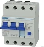
Doepke FI-/LS-Kombinationen DRCBO 4 B25/0.03/3N-A Handbuch

Das Doepke DRCBO 4 B25/0.03/3N-A kombiniert Fehlerstromerkennung und Überstromschutz in einem kompakten, schienenmontierbaren Gerät, das für moderne elektrische Installationen ausgelegt ist. Hergestellt nach VDE- und DIN-EN-Normen schützt dieses Typ-B DRCBO (AC/DC-empfindlich) vor Erdfehlern und Überlastungen und ermöglicht eine unkomplizierte Installation, Prüfung und Wartung. Es eignet sich besonders für Systeme mit elektronischen Lasten wie Frequenzumrichtern, Wechselrichtern und anderen Geräten, die Ableitströme erzeugen können.

Dieses Modell unterstützt vereinfachte Isolationsprüfungen, wenn die Versorgung an die ungeraden Klemmen geführt wird, sodass Messungen von der Systemseite bei ausgeschaltetem Schalter möglich sind. Das Gerät verfügt über einen für den Benutzer zugänglichen Prüftaster für schnelle Funktionsprüfungen und eine grüne Front-LED, die die aktive AC/DC-empfindliche Fehlerstromerkennung anzeigt. Leuchtet die LED nicht, bleibt nur die Typ-A-Erkennung aktiv und es sind weitere Prüfungen erforderlich.

Da elektronische Geräte, EMC-Filter und geschirmte Motorkabel hohe kapazitive Ableit- oder Transientenströme erzeugen können, wird eine sorgfältige Systemplanung empfohlen. Übermäßige Ableitströme oder Resonanzen mit vorgelagerten EMC-Filtern können unerwünschtes Auslösen verursachen. Empfohlene Gegenmaßnahmen sind die Begrenzung nachgelagerter elektronischer Lasten, die Beachtung der Herstellerhinweise für Frequenzumrichter, der Einsatz von Sinusfiltern bei Bedarf, kurze Einschalttransienten und die Vermeidung ungeeigneter Verdrahtungspraktiken.

Die Installation ist für qualifizierte Elektrofachkräfte vorgesehen: Das Gerät wird auf TS-35-DIN-Schienen montiert, erfordert eine korrekte Anschlussverdrahtung gemäß dem aufgedruckten Schaltplan, und Aluminiumleiter sollten vor dem Anschluss abgeschabt und gefettet werden. Das Handbuch warnt davor, sichtbar beschädigte Geräte zu installieren, und betont den Betrieb in nicht korrosiver Umgebung. Regelmäßige Prüfungen—mindestens alle sechs Monate für feste Installationen und häufiger für mobile Systeme—sind erforderlich; schlägt das Gerät bei Prüfungen nicht an, muss es sofort ersetzt werden.

Die Garantie deckt fachgerecht installierte, unveränderte Geräte für die gesetzliche Frist ab, ausgenommen Transportschäden, unsachgemäße Verwendung, Kurzschlüsse oder Überlastungen. Unbefugtes Öffnen hebt die Garantie auf. Die Entsorgung erfolgt gemäß EU-WEEE-Vorschriften.

Hinweise:

  • Verwenden Sie für vereinfachte Isolationsprüfungen bei Typ-B-Geräten die ungeraden Versorgungsklemmen.
  • Beachten Sie bei Frequenzumrichtern die maximalen Schirmkabellängen und prüfen Sie gegebenenfalls den Einsatz von Sinusfiltern, um aus Ableitströmen resultierende Auslösungen zu vermeiden.
  • Ersetzen Sie das Gerät, wenn es den Test nicht besteht oder wenn die grüne AC/DC-LED trotz ordnungsgemäßer Betriebsspannung nicht leuchtet.
M: OA-GPT-5-NAN

© Copyright 2026 Manual.ly