Manual.ly Logo

Doepke DFS 4 125 Bedienungsanleitung

0,0 · 0 Bewertungen

PDF-Handbuch · 2 Seiten

Deutsch

M: OA-GPT-5-NAN
Seite

/ 2

Loading...
8433110423a6137528e1a3ee47f3379713af page 2
type A residual currents is guaranteed. If this is the case, it should be checked rst
if there is operating voltage of min. 50 V AC between two active conductors. If this
voltage is present at the switch and the LED does not illuminate, the residual current
circuit-breaker must be replaced.
Insulation test
The insulation test should be carried out using test devices according to
DIN EN 61557-2. To carry out a simple insulation test for the electrical system, we
recommend supplying power ‘from above’ for type-B switches. This means only
the switch needs to be switched oduring the test and the measurement can take
place on the system side. Performing an insulation test when the residual cur-
rent circuit-breaker is switched on or on the side with the odd-numbered termi-
nals can lead to erroneous measurement values as a result of the internal adaptor.
In this case, we recommend disconnecting the switch for the duration of the test.
Exception:
An insulation test of up to 1000 V can also be carried out on the upper odd terminals
without the need to disconnect beforehand for all AC-DC sensitive residual current
circuit-breakers in the ISO HD ‘ISΩ HD’ design.
Important information on operating an AC-DC sensitive residual current circuit-
breaker (DFS 2/4 B/B+) with electronic equipment
(such as frequency converters, inverters etc.)
1. Electronic equipment and its associated EMC protective provisions,
such as integrated or in series-connected EMC lters, as well as shielded cables,
can produce high capacitive leakage currents.
2. The maximum number of items of electronic equipment connected
down stream of the DFS 2 B/DFS 4 B is based on the level of leakage currents that
occur. Excessive leakage currents may lead to undesired tripping. Relevant infor-
mation concerning the leakage currents that are produced can be requested from
the manufacturers of the electronic equipment.
3. During operation with frequency converters, long, shielded motor cables can re-
sult in high leakage currents, which may lead to undesired tripping. If necessary,
a sinusoidal output lter should be connected to the frequency converter output
terminals (before the shielded motor cable).
4. When switching electrical systems with electronic equipment on and o,
it is possible that very high surge leakage currents will be produced, which will
lead to tripping should they continue for the relevant duration. The switch-on and
switch-o operations should be kept as short as possible. Quick-switching, all-
pole contactors or switches with stored energy operating mechanisms are suit-
able (manual rotary switches should not be used).
5. According to the instructions, a 3-conductor EMC lter should only be connected
in series with the relevant electronic equipment. To avoid impairing the lter ef-
fect, under no circumstances should further single-phase consumers such as in-
candescent bulbs be connected on the output side of the EMC lter.
6. As a rule, dierent clock frequencies (chopper) can be selected in the case of
electronic equipment. In the worst-case scenario, the clock frequency may lead
to a tendency to oscillation in an upstream EMC lter and therefore to greatly
increased leakage currents, which then cause the DFS 2/4 B to trip. In this case,
the clock frequency must be changed.
7. Frequency converters with an integrated EMC lter often only allow a maximum
shielded motor cable length of 5 to 10 m. Longer cable lengths lead to greatly
increased leakage currents and can render the integrated EMC lter ineective.
The manufacturer's specications must always be observed for the frequency
converter.
Guarantee
All professionally installed, unaltered devices are covered by warranty during the
statutory guarantee period from the day of purchase by the end user. The guarantee
does not apply to damage incurred during transport or caused by short-circuit, over-
loading or improper use. For defects in workmanship or material that are discovered
within the warranty period, the company will provide repair or replacement free of
charge. The warranty will be rendered null and void if the device is opened without
authorisation.
Wiring diagrams
2 4
1 3
~
1/N 7/N3 5
8/N
2/N
4 6
~
S two-pole (grey: type B only) S four-pole, neutral on left or right,
depending on device version
(grey: type B only)
Installation and operating instructions
for residual current circuit-breakers
of series DFS 2 and DFS 4
These installation and operating instructions are aimed at qualied
electrical specialists. The installation of devices of this type is not ap
-
propriate for electrical laypersons due to the considerable potential
dangers. These installation and operating instructions must be re
-
tained, so that they can be referred to at a later stage. The operator of
the electrical installation must be informed about the use and function
of this protective device.
Application instructions and warnings
The following notes and warnings must be observed in order to ensure safe opera-
tion:
1. Devices with visible damage must not be installed or used.
2. Operation must only occur under normal ambient conditions free of corrosive
gases in order to preserve the correct tripping function in the long term. Cor
-
rosive gases are chlorine, ammonia and sulphurous air, for example. Residual
current circuit-breakers with "HD" specication are recommended for environ
-
ments aected by corrosive gases.
3. The user must be made aware of regular function testing using the test key T.
4. The function test with the test key is not a substitute for regular testing of the
electrical system.
5. Erroneous tripping due to operation related leakage currents or atmos-
pheric interference cannot be ruled out with absolute certainty. The conse-
quences must be considered and countermeasures taken where necessary.
Selective residual current circuit-breakers as well as surge protection measures
and system optimisations can provide a remedy.
6. If the RCCB cannot be switched on, or if the consumer network is not connected,
the device must be replaced.
7. Disposal is subject to the statutory regulations of the European Union (WEEE/
German Electrical and Electronic Equipment Act).
For further information and data sheets, please visit www.doepke.de and search by
the article number or scan the QR code on the front of the housing.
Intended use:
DFS 2 and DFS 4 series protective devices are residual current circuit-breakers
without integrated overcurrent protection. They provide protection through auto-
matic switch-oin electrical systems, e.g. in accordance with VDE 0100 part 410.
They meet the requirements for residual current protection in accordance with their
characteristics on the name plate. The switch-o function can be tested using a
push-button which is also accessible to laypersons. Regular testing can also increase
the endurance of the circuit-breaker, as the mechanism of the latch is moved when
tripped in addition to the electrical test.
Electrical connection and installation:
The electrical connection must be as shown in the wiring diagram and must comply
with the terminal designation on the device. With type-B devices, it is preferable for the
power to be supplied to the odd-numbered terminals (simplied insulation measure-
ment). If the device is to be operated without using all poles, it is essential (in order to
ensure the connection is correct) to observe the position of the test key as per the wir-
ing diagram and the operating voltage range of the test circuit in accordance with the
data sheet. DFS 4 devices have an N-left design as standard. N-right devices have an
‘R’ in their designation. Scrape and grease aluminium conductors immediately before
connection. The device must be installed on a mounting rail (TS 35) according to
DIN EN 60715 in distribution boards that must ensure protection against direct con-
tact (which may be required depending on the location of use) and protection against
environmental inuences.
Testing and functional check
A simple function test with the assistance of test key T should be carried out after
the mains voltage and the circuit-breaker are switched on. When the key is pressed,
the DFS 2/DFS 4 must disconnect without delay; the toggle will then be in the centre
position. Resetting to position ‘1’ is only possible if the toggle has rst been moved
down to position ‘0’. The operation indicator beneath the toggle indicates the status
of the contacts: red = closed, green = open. This test must be carried out at least
every six months where the device is used as intended and must be repeated every
working day for non-stationary systems according to the regulation. If tripping does
not occur, the device must be replaced immediately. The operator must be informed
of this. All additional tests are covered by the prescribed acceptance test. Tests
should be carried out according to DGUV Regulation 3 (BGV A3) depending on the
location of use.
The green LED on the front of the housing of the DFS 2 B/DFS 4 B AC-DC sensitive
residual current circuit-breaker indicates that the AC-DC sensitive residual current
detection is active. If the LED does not illuminate, then only tripping in the event of
Doepke
3930298
|
02/2020
|
Doepke Schaltgeräte GmbH, Stellmacherstraße 11, D-26506 Norden
DE EN

Chatten Sie mit Ihrem Doepke DFS 4 125-Handbuch mithilfe von KI

Erhalten Sie sofortige KI-Antworten aus Ihrem Doepke DFS 4 125-Handbuch

Fragen Sie alles über Doepke DFS 4 125. Antworten stammen aus diesem Handbuch, mit den Seiten, auf denen sie basieren.

DFS 4 125 Wartungsplan

Erinnere mich, wenn eine Wartung faellig ist
Alle sechs Monate
Funktionsprüfung des Fehlerstromschutzschalters

Testtaste T drücken, um zu verifizieren, dass das Gerät verzögerungsfrei abschaltet. Bei Ausbleiben des Auslösers sofort ersetzen.

An jedem Arbeitstag
Prüfung nicht stationärer Systemgeräte

Funktionsprüfung mit Testtaste T an jedem Arbeitstag für nicht stationäre Systeme gemäß Vorschriften wiederholen.

Kostenlose Wartungserinnerungen

Abgestimmt auf Ihr Kaufdatum. Immer kostenlos, jederzeit abbestellbar.

Mit dem Absenden stimmen Sie der Datenschutzerklarung zu. Sie konnen sich in jeder E-Mail mit einem Klick abmelden.
M: QW-35-FL

Stellen Sie eine Frage

0/1000

Empfehlen Sie DFS 4 125?

Ja Nein

Häufig gestellte Fragen

A

AC/DC-empfindlich bedeutet, dass das Gerät sowohl Wechselstrom-Fehlerströme als auch pulsierende Gleichstrom-Fehlerströme erkennt und somit für Systeme mit Frequenzumrichtern, Invertern und anderen elektronischen Lasten geeignet ist, die nicht-sinusförmige Leckströme erzeugen können.

Ist diese Antwort hilfreich?

A

Bei normalem stationärem Betrieb mindestens alle sechs Monate. Bei nicht-stationären oder regulierten Installationen können tägliche Prüfungen oder Prüfungen nach lokalen Vorschriften erforderlich sein. Löst das Gerät bei der Prüfung nicht aus, muss es sofort ersetzt werden.

Ist diese Antwort hilfreich?

A

Bei Standardgeräten sollten Isolationsprüfungen nach DIN EN 61557-2 erfolgen und können ein Abtrennen des Geräts erfordern, um fehlerhafte Messwerte zu vermeiden. Einige ISO-HD-Varianten erlauben Isolationsprüfungen bis 1000 V an bestimmten Klemmen ohne vorheriges Abtrennen.

Ist diese Antwort hilfreich?

A

Elektronische Geräte und EMV-Maßnahmen (Filter, geschirmte Leitungen) können hohe kapazitive oder einschaltbedingte Leckströme erzeugen. Übermäßige Leckströme oder ungünstige Wechselwirkungen mit EMV-Filtern können zu Fehlauslösungen führen; Abhilfemaßnahmen sind unter anderem Anpassung der Filtereinstellungen, Einsatz von Sinus-Ausgangsfiltern oder Reduzierung der Kabellängen.

Ist diese Antwort hilfreich?

A

Nein. Der DFS 4 125 ist ein Fehlerstrom-Schutzelement ohne integrierten Überstromschutz und muss zusammen mit geeigneten Überstromschutzeinrichtungen entsprechend Systementwurf und Normen installiert werden.

Ist diese Antwort hilfreich?

A

Überprüfen Sie zunächst, ob eine Mindestbetriebs-Spannung (ca. 50 V AC) zwischen den aktiven Leitern anliegt. Ist Spannung vorhanden und die LED bleibt aus, sollte das Gerät ersetzt werden, da die AC/DC-Detektion möglicherweise nicht aktiv ist.

Ist diese Antwort hilfreich?

A

Ja. Aluminiumleiter sollten unmittelbar vor dem Anschluss abgeschabt und gefettet werden, um zuverlässigen Kontakt zu gewährleisten und oxidationbedingte Anschlussprobleme zu vermeiden.

Ist diese Antwort hilfreich?

M: OA-GPT-5-NAN

Vorteile und Nachteile

Vorteile

  • AC/DC-empfindliche Erkennung, geeignet für Installationen mit elektronischen Antrieben und Invertern.
  • Klare Zustandsanzeige und zugänglicher Testtaster für regelmäßige Funktionsprüfungen.
  • Design ermöglicht vereinfachte Isolationsprüfung bei Versorgung an ungeraden Klemmen (Typ B).
VS

Nachteile

  • Anfällig für Fehlauslösungen durch hohe Leckströme, die von EMV-Filtern oder langen geschirmten Leitungen erzeugt werden.
  • Enthält keinen Überstromschutz; erfordert Abstimmung mit vorgeschalteten Geräten.
  • Erfordert fachgerechte Installation und regelmäßige Prüfung; nicht für Laieninstallation geeignet.
M: OA-GPT-5-NAN

Produkt Spezifikation

Typ

RCCB

Polzahl

3 + N

Bemessungsspannung

400 V

Bemessungsstrom

125 A

Schutzart

IP20

Breite

72 mm

Teilungseinheiten

4

M: GO-GEM-FL-25

Produkt Beschreibung

Doepke DFS 4 125 — Zuverlässiger AC/DC-empfindlicher Fehlerstromschutz

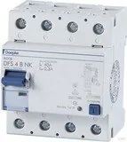
Der Doepke DFS 4 125 ist ein robuster AC/DC-empfindlicher Fehlerstrom-Schutzschalter (RCCB), der für anspruchsvolle Installationen entwickelt wurde, bei denen eine zuverlässige Fehlerstromerkennung und ein sicheres automatisches Abschalten essenziell sind. Für den professionellen Elektrobereich gebaut, bietet die DFS 4-Serie eine empfindliche Erkennung sowohl von Wechselstrom- als auch von pulsierenden Gleichstromfehlern und integriert Funktionen, die Prüfung, Installation und Wartung in Industrie- und Gewerbeumgebungen vereinfachen.

Hauptmerkmale und praktische Anwendung

Der DFS 4 125 unterstützt Allpol- und Mehrpol-Installationen, mit klarer Anschlusskennzeichnung und Anschlussdiagrammen, um korrekte Verdrahtung sicherzustellen. Type-B-Ausführungen (AC/DC-empfindlich) werden empfohlen, wenn elektronische Lasten wie Frequenzumrichter und Inverter vorhanden sind. Das Gerät bietet eine sichtbare Zustandsanzeige unter dem Schalter (rot = geschlossen, grün = offen) und einen zugänglichen Testtaster für einfache Funktionsprüfungen. Zur vereinfachten Isolationsprüfung wird bei Type-B-Geräten die Versorgung an den ungeraden Klemmen bevorzugt, wodurch das Trennen nachgeschalteter Stromkreise reduziert wird.

Die Installation ist für qualifizierte Elektrofachtkräfte vorgesehen und der Schutzschalter wird auf einer standardmäßigen TS 35 Hutschiene montiert. Aluminiumleiter sollten vor dem Anschluss abgeschabt und gefettet werden. Das Produkt ist für Umgebungen ohne korrosive Gase spezifiziert; eine HD-Variante ist für aggressive Atmosphären erhältlich. Das Gerät enthält keinen Überstromschutz und muss mit geeigneten vorgeschalteten Überstromschutzeinrichtungen entsprechend den Systemanforderungen kombiniert werden.

Wechselwirkung mit elektronischen Geräten

Bei Verwendung mit elektronischen Lasten (Frequenzumrichtern, Invertern, EMV-Filtern, geschirmten Motorleitungen) erfordert der DFS 4 125 Aufmerksamkeit bezüglich Leckströmen und EMV-Maßnahmen. Integrierte oder externe EMV-Filter und lange geschirmte Leitungen können kapazitive Leckströme erzeugen, die zu unerwünschtem Auslösen führen. Maßnahmen umfassen die Beschränkung nachgeschalteter elektronischer Geräte auf solche mit spezifizierten Leckstromwerten, den Einsatz von Sinusfiltern an den Ausgängen von Frequenzumrichtern, die Einhaltung maximaler geschirmter Kabellängen (typisch 5–10 m für Umrichter mit integrierten EMV-Filtern) und die Auswahl geeigneter Schaltgeräte, um lange Einschaltspitzenleckströme zu minimieren.

Prüfung, Wartung und Garantie

Routinemäßige Funktionsprüfungen mittels Testtaste werden mindestens alle sechs Monate empfohlen (bei nicht-stationären Installationen häufiger). Wenn das Gerät bei der Prüfung nicht auslöst oder sich nicht einschalten lässt, muss es ersetzt werden. Isolationsprüfungen sollten nach DIN EN 61557-2 erfolgen und können bei bestimmten ISO-HD-Varianten bis zu 1000 V ohne Abtrennung durchgeführt werden. Das Produkt beinhaltet eine gesetzliche Standardgarantie für fachgerecht installierte, unveränderte Geräte; ein nicht autorisiertes Öffnen hebt die Garantie auf.

Hinweise

  • Nur für qualifizierte Elektroinstallateure bestimmt.
  • Sichtbar beschädigte Geräte nicht verwenden; bei Defekt sofort ersetzen.
  • Herstellerspezifikationen für EMV-Filter und Frequenzumrichterverkabelung beachten.
M: OA-GPT-5-NAN

© Copyright 2026 Manual.ly