Manual.ly Logo

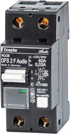
Doepke DFS 2 040-2/0,03-F Audio Bedienungsanleitung

0,0 · 0 Bewertungen

PDF-Handbuch · 2 Seiten

Deutsch

M: QW-35-FL
Seite

/ 2

Loading...
822d0984b91f6a0f9d7a9d6a6caa89c13178 page 2
Recommendations for the power supply of audio systems in conjunction with the
DFS F Audio, with a view to improving sound:
The following recommendations must only be implemented by an authorised and
qualied electrical specialist, who is familiar with the applicable national installation
regulations. The recommendations exclusively refer to the circuit for connecting an
audio system. Priority should always be given to ensuring that electrical installations
are correctly implemented in line with the applicable installation regulations, over
any sound objectives.
» Use an outer conductor (L1, L2 or L3) that is used by as few other electrical
consumers (e.g. lights or household appliances) as possible.
» If possible, use a separate installation cable from the distribution installation
to the installation socket to which the audio system is connected. No further
electrical consumers should be connected to this circuit.
» When using multiple residual current circuit-breakers in a distribution installation,
the DFS F Audio should be connected on the input side, if possible directly, to the
connection cables from the meter board. Further residual current circuit-breakers
can then be connected on the input side, e.g. with suitable busbars.
» Connect the phase conductor to which your audio system is connected to the
output side (load side) of the DFS F Audio via a suitable overcurrent protective
device.
» Through use of a busbar fork, it is also possible to connect to the upper wiring level
for the DFS F Audio. This renes the sound image somewhat but does reduce the
volume a little.
» When connecting the neutral conductor to which your audio system is connected,
avoid having a lot of terminal positions in the neutral conductor path. If necessary,
it is possible to connect the neutral conductor directly to the neutral conductor
pole terminal on the output side (load side) of the DFS F Audio instead of to
the neutral conductor rail on the distribution board. This adds volume and
authenticity to the audio image without losing precision.
» If the installation cable to your audio system in the distribution installation needs
to be extended or connected to installation terminals, avoid using ferromagnetic
materials (e.g. copper-covered steel) as direct live parts. However, parts that
are not directly conductive that are used to mechanically secure electrical
conductors, e.g. clamping screws made from ferromagnetic material, have no
adverse eect on sound.
Hints:
» The audio image may initially seem rather unsettled following installation and
wiring work on the distribution board. This will subside after a few operating
hours.
» In comparison to standard residual current circuit-breakers, the DFS F Audio
provides a stable and clear audio image, without lessening the volume or
musicality. The sound is, however, aected by many factors relating to an audio
system’s power supply and, of course, by the components in an audio system and
can therefore vary.
» If mains lters are in place at the output side (load side) of the DFS F Audio, in
many cases, depending on the type of lter, it may be necessary to disconnect
them from the mains if the audio image is clearly dened but too thin.
Break-in time of the DFS F Audio:
» Immediately after it is rst commissioned, the audio image can seem more
lightweight, particularly in the low range.
» After around two to three operating hours, the audio image increasingly gains
in volume.
» The full potential of the sound is achieved after around 50–100 operating hours.
An audio system does not necessarily have to be active during this time.
» The residual current protection function of the DFS F Audio is of course available
immediately after installation and at all times.
Wiring diagrams
1 3
2 4
N 3 5 7
N 4
6
8
1 3 5 N
2 4
6
N
S two-pole S four-pole,
neutral conductor on
the left
S four-pole,
neutral conductor on
the right
Installation and operating instructions
for two-/four-pole residual current circuit-breakers
in the DFS F Audio series
These installation and operating instructions are aimed at qualied
electrical specialists. The installation of devices of this type is not
appropriate for electrical laypersons due to the considerable potential
dangers. These installation and operating instructions must be
retained, so that they can be referred to at a later stage. The operator
of the electrical installation must be informed about the use and
function of this protective device.
Application instructions and warnings
The following notes and warnings mus t be obser ved in order to ensure safe operation:
1. Devices with visible damage must not be installed or used.
2. Operation must only occur under normal ambient conditions free of corrosive
gases in order to preserve the correct tripping function in the long term.
Corrosive gases are chlorine, ammonia and sulphurous air, for example.
3. The user must be made aware of regular function testing using the test key T.
4. The function test with the test key is not a substitute for regular testing of the
electrical system.
5. Erroneous tripping due to operation related leakage currents or atmospheric
interference cannot be ruled out with absolute certainty. The consequences must
be considered and countermeasures taken where necessary.
6. If the RCCB cannot be switched on, or if the consumer network is not connected,
the device must be replaced.
7. Disposal is subject to the statutory regulations of the European Union (waste of
electrical and electronic equipment (WEEE)).
Further information and product data sheets can be found at www.doepke.de.
Intended use:
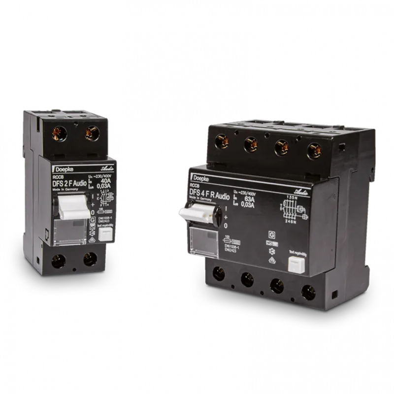
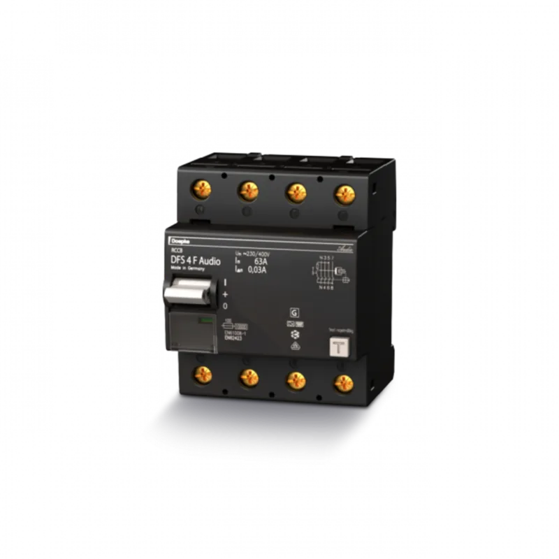
DFS 2 and DFS 4 series protective devices are residual current circuit-breakers
without integrated overcurrent protection. They provide protection through
automatic switch-o in electrical systems, e.g. in accordance with VDE 0100 part
410. They meet the requirements for residual current protection in accordance with
their characteristics on the name plate. The switch-ofunction can be tested using
a push-button which is also accessible to laypersons. Regular testing can increase
the endurance of the circuit-breaker, as the mechanism of the latch is moved when
tripped in addition to the electrical test.
Electrical connection and installation:
The electrical connection must be as shown in the wiring diagram and must comply
with the terminal designation on the device. If the device is to be operated without
using all poles, it is essential (in order to ensure the connection is correct) to observe
the position of the test key as per the wiring diagram and the operating voltage
range of the test circuit in accordance with the data sheet. DFS 4 devices have a
N-left design as standard. N-right devices have a ‘R’ in their designation. The device
must be installed on a mounting rail (TS 35) according to DIN EN 60715 in distribution
boards that have to ensure protection against direct contact (which may be required
depending on the location of use) and protection against environmental inuences.
Testing and functional check
A simple function test with the assistance of test key T should be carried out after
the mains voltage and the circuit-breaker are switched on. When the key is pressed,
the DFS 2/DFS 4 must disconnect without delay; the toggle is then in centre position.
Resetting to position ‘1’ is only possible if the toggle has rst been moved down to
position ‘0’. The operation indicator beneath the toggle indicates the status of the
contacts: red = closed, green = open.
This test must be carried out at least every six months where the device is used as
intended and must be repeated every working day for non-stationary systems
according to the regulation. If tripping does not occur, the device must be replaced
immediately. The operator must be informed of this. All additional tests are covered
by the prescribed acceptance test. Tests should be carried out according to DGUV
Regulation 3 (BGV A3) depending on the location. The insulation test should be
carried out using test devices according to DIN EN 61557-2.
Guarantee
All professionally installed, unaltered devices are covered by warranty during the
statutory guarantee period from the day of purchase by the end user. The guarantee
is not applicable to damage incurred during transport or caused by short-circuit,
overloading or improper use. Should any defects in workmanship or material
be discovered within the warranty period, the company will provide repair or
replacement free of charge. The warranty will be rendered null and void if the device
is opened without authorisation.
Doepke
3930292
|
11/2019
|
Doepke Schaltgeräte GmbH, Stellmacherstraße 11, D-26506 Norden
DE EN

Chatten Sie mit Ihrem Doepke DFS 2 040-2/0,03-F Audio-Handbuch mithilfe von KI

Erhalten Sie sofortige KI-Antworten aus Ihrem Doepke DFS 2 040-2/0,03-F Audio-Handbuch

Fragen Sie alles über Doepke DFS 2 040-2/0,03-F Audio. Antworten stammen aus diesem Handbuch, mit den Seiten, auf denen sie basieren.

DFS 2 040-2/0,03-F Audio Wartungsplan

Erinnere mich, wenn eine Wartung faellig ist
Täglich (werktags)
Funktionstest für nicht stationäre Systeme durchführen

Wiederholen Sie bei Geräten, die in nicht stationären Systemen installiert sind, den Funktionstest mit dem Prüftaste jeden Werktag gemäß den Vorschriften.

Halbjährlich
Funktionstest mit Prüftaste T durchführen

Drücken Sie die Prüftaste T, um zu überprüfen, ob das Gerät ohne Verzögerung auslöst. Wenn es nicht auslöst, ersetzen Sie das Gerät sofort.

Kostenlose Wartungserinnerungen

Abgestimmt auf Ihr Kaufdatum. Immer kostenlos, jederzeit abbestellbar.

Mit dem Absenden stimmen Sie der Datenschutzerklarung zu. Sie konnen sich in jeder E-Mail mit einem Klick abmelden.
M: qwen/qwen3.8-flash

Stellen Sie eine Frage

0/1000

Empfehlen Sie DFS 2 040-2/0,03-F Audio?

Ja Nein

Häufig gestellte Fragen

A

Das Gerät erreicht sein volles Potenzial nach ungefähr fünfzig bis einhundert Betriebsstunden. Der Pegel steigt innerhalb von zwei bis drei Stunden merklich an. Ein unruher Klang ist normal zu Beginn und klingt schnell nach.

Ist diese Antwort hilfreich?

A

Nein, die Installation ist für elektrotechnische Laien aufgrund erheblicher potenzieller Gefahren ungeeignet. Nur qualifizierte Elektriker, die mit nationalen Vorschriften vertraut sind, sollten die Montage durchführen.

Ist diese Antwort hilfreich?

A

Wenn kein Auslösen nach Drücken der Testtaste erfolgt, muss das Gerät sofort ersetzt werden. Der Betreiber muss über diese Anforderung zur Sicherheitskonformität informiert werden.

Ist diese Antwort hilfreich?

A

Ja, der Schutz gilt für professionell installierte und unveränderte Geräte gemäß gesetzlicher Gewährleistung. Sie schließt Schäden durch Transport, Kurzschlüsse oder unsachgemäßen Gebrauch aus. Herstellermängel werden kostenlos repariert oder ersetzt.

Ist diese Antwort hilfreich?

A

Nein, die DFS-Serie verfügt nicht über integrierten Überstromschutz. Sie dient ausschließlich als Reststrom-Schutzschalter zum Schutz durch automatische Abschaltung.

Ist diese Antwort hilfreich?

A

Zur Klangverbesserung den Neutralleiter direkt zum Lastseitigen Pol-Anschlussterminal, statt zur Verteilungskasten-Schiene. Vermeiden Sie übermäßige Terminalsituationen im Pfad.

Ist diese Antwort hilfreich?

A

Der Betrieb muss unter normalen Bedingungen stattfinden, frei von korrosiven Gasen wie Chlor, Ammoniak oder schwefelhaltiger Luft, um die Auslösefunktion langfristig zu bewahren.

Ist diese Antwort hilfreich?

M: QW-35-FL

Vorteile und Nachteile

Vorteile

  • Stabilisiert und klarstellt das Klangbild ohne Verringerung von Lautstärke oder Musizalität verglichen zu Standardgeräten.
  • Reststromschutzfunktion bleibt sofort bei Installation aktiv und jederzeit.
  • Einfache Funktionsprüfung über Druckknopf hilft, Mechanismusintegrität zu erhalten und Widerstandsfähigkeit zu erhöhen.
  • Direkter Neutralleiteranschluss fügt Lautstärke und Authentizität hinzu, ohne Präzision zu verlieren.
  • Montiert leicht auf TS 35 Schienen in Übereinstimmung mit DIN EN 60715 Standards für Verteilerschränke.
VS

Nachteile

  • Erfordert Installation durch autorisierte und qualifizierte Elektrofachleute wegen Gefahrenpotenzial.
  • Initiales Klangbild mag zunächst unsicher oder leichtgewichtig wirken, bis Einspielzeit abgeschlossen ist.
  • Existierende Netzfilter müssen möglicherweise getrennt werden, falls Klang zu dünn oder falsch definiert wird.
  • Müssen ferromagnetische Materialien in direkten stromführenden Teilen vermeiden, die negativen Einfluss auf Klang haben können.
  • Kein integrierter Überstromschutz, sodass separates Gerät für diese spezifische Sicherheitsfunktion benötigt wird.
M: QW-35-FL

Produkt Spezifikation

Typ

RCCB

Polezahl

1 + N

Nennspannung

230 V

Nennstrom

40 A

Nennfehlerstrom

30 mA

Fehlerstromtyp

F

Schutzart

IP20

Breite

3,61 cm

Modulanzahl

2

M: QW-35-FL

Produkt Beschreibung

Steigerung der Audio-System-Stromqualität mit Doepke Technologie

Die Erzielung überlegener Klangwiedergabe hängt oft mehr ab von hochwertigen Lautsprechern oder Verstärkern. Die elektrische Infrastruktur spielt eine kritische Rolle bei der Aufrechterhaltung der Signalreinheit. Das Doepke Reststrom-Schutzschalter DFS 2 040-2/0,03-F Audio Handbuch beschreibt, wie dieses spezifische Gerät zu saubererer Stromlieferung für sensible Audiophil-Setups beiträgt. Im Gegensatz zu Standard-Schutzschaltern liegt der Fokus dieses Modells stark auf der Minimierung von Störungen in der Stromkreisschaltung, die direkt mit den Audiosystemkomponenten verbunden ist.

Eine sachgerechte Installation ist sowohl für die Sicherheit als auch für die Leistungsergebnisse von größter Wichtigkeit. Qualifizierte Elektriker müssen alle Anschlüsse vornehmen, um sicherzustellen, dass nationale Vorschriften eingehalten werden, bevor Klangaspekte berücksichtigt werden. Die Verwendung eines separaten Außenleiters reduziert Störgeräusche von Haushaltsgeräten wie Lampen beträchtlich. Der direkte Anschluss an die Eingangsseite des Zählerschirms hilft, die Audioschaltung effektiv von allgemeinen Verteilungsbelastungen zu isolieren. Neutralleiter sollten idealerweise direkt zum Lastseitigen Anschlussterminal verknüpft werden, statt zu einer gemeinsamen Verteilungsschiene, um Lautstärke und Natürlichkeit zu verbessern, ohne Präzision zu verlieren.

Benutzer sollten eine Anfangseinspielzeit bezüglich akustischer Merkmale beachten. Beim ersten Inbetriebnehmen wirkt der Klang eventuell leichtgewichtig, besonders in den tiefen Frequenzbereichen. Innerhalb von zwei bis drei Stunden Betrieb erhöhen sich Pegel merklich. Volles Potenzial ist nach fünfzig bis hundert Betriebsstunden Nutzung erreicht. Während dieser Zeit bedarf das Audiosystem nicht unbedingt, Musik stetig zu spielen, um die Elektronik zu konditionieren. Die Reststromschutzfunktion bleibt sofort nach Installation aktiv und bleibt jederzeit online.

Vergleiche mit Standardgeräten zeigen, dass dieser Schutzschalter das Klangbild stabilisiert und klarstellt, dabei Gesamtmusikalität bewahrend. Jedoch müssen existierende Netzfilter auf der Ausgabeseite eventuell getrennt werden, falls der Klang zu dünn wird, trotz guter Definition. Regelmäßige Prüfung via Testtaste T sichert Sicherheit und erhält interne Mechanismusintegrität. Dieses Gerät erfordert Betrieb in korrosionsgasfreier Umgebung, um chemische Zersetzung zu vermeiden. Entsorgung folgt strengen EU WEEE Richtlinien. Für detaillierte Verkabelungspläne einschließlich zwei-poliger und vier-poliger Konfigurationen ist Konsultation der offiziellen Dokumentation essenziell für korrekte Einrichtung. Professionelle Wartung garantiert langfristige Zuverlässigkeit und konsistente Klangleistungsvorteile während der gesamten Produktlebensdauer.

M: QW-35-FL

© Copyright 2026 Manual.ly