Manual.ly Logo

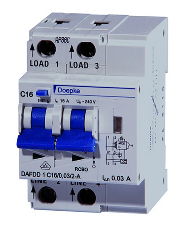
Doepke DAFDD 1 C16/0,03/2-A Bedienungsanleitung

0,0 · 0 Bewertungen

PDF-Handbuch · 2 Seiten

Deutsch

M: QW-35-FL
Seite

/ 2

Loading...
b3684454df5ca073e0dfd139516fad23a3ea page 2
Functional inspections
Testing the residual current circuit-breaker
A functional inspection of the residual current circuit-breaker itself is possible with
connected mains voltage by pressing the test button T. As in commercial use (DGUV
regulation 3), it should be carried out at least every six months in the case of station-
ary systems and should be repeated every working day in the case of non-stationary
systems. The test button is pressed to conduct internal testing on the residual cur-
rent device. Pressing this button regularly may extend the reliability of the device
in the long term, as it means that the mechanical components are moved and the
electronic components are tested. Pressing the test button and switching the device
back on following a successful test can be done by an ordinary person and does not
require expert electrotechnical knowledge.
The switch is defective if it does not trip when the test button is pressed,
or if there is a delay before this happens. In the event of a fault, adequate
protection may no longer be guaranteed!
AFD unit testing
The AFD unit constantly tests the incoming high-frequency signals and the results
from the controller for plausibility. If anything is conspicuous during this self-testing,
the switch will trip. The internal fault will be displayed as a blink code via the LED
after the device is switched back, then switches from red to yellow permanently.
This restart feature makes 24-hour operation possible, until the switch trips again.
-
ers that the AFD unit stopped working.
Arc fault monitoring is not guaranteed during 24-hour operation! All RCBO
functions will be available, independently of the AFD unit.
DAFDD 1 displays

Tripping due to RCBO
Residual current
The rectangular display located centrally
below the toggle switches from white to
blue.
White: OK (with supply connection and
disconnection)
Blue: triggered by residual current
Line protection
Position indicating devices are required
to identify trips caused by line protec-
tion. The triangle displays below the
toggle switch between green and red, as
described below. The display for residual
current remains white.

Red: device switched on
Tripping due to AFD unit
The rectangular display located centrally
below the toggle switches from white to
blue. The LED displays a (yellow) blink
code after the device is switched back on.
The unit repeats this three times, then
switches permanently to green (normal
operation) or switches yellow-red (the
AFD unit has stopped working during
24h operation). Refer to the table ‘Expla-
nation of AFD unit error codes’ for more
about the error that is displayed here.
AFD UnitRCBO
AFD UnitRCBO
AFD UnitRCBO
Installation and operating instructions
for residual current operated circuit-breakers
with integral over-current release and arc fault
protection equipment (series DAFDD 1)

electrical specialists. The installation of devices of this type is not
appropriate for electrical laypersons due to the considerable poten-
tial dangers. The installation and operating instructions must be
kept so that they can be referred to at a later stage. The operator of
the electrical installation must be informed about the use and func-
tion of this protective device.
Intended use
DAFDD 1 series switching devices are residual current operated circuit-breakers with
integral over-current release (RCBO, also known as a FI/LS combination) and arc fault

DAFDD1 meet requirements both for fault current and overcurrent protection and



aside, the DAFDD1 also monitors internal voltage to protect connected consumers
          
270 V AC.
Application
The DAFDD 1 are designed solely for use in single-phase alternating current systems
with a rated voltage of 230 V and a rated frequency of 50 Hz. They are not intended
for use in DC networks.
Application instructions and warnings
 Devices with visible damage must not be installed or used.
 Without any additional protective housing, protective switching devices should
only be stored and operated in a dry, low-dust environment. An aggressive
atmosphere must also be avoided.
 Protection against direct contact according to protection class 2 must be ensured
with the assistance of the associated distribution board or device covers.
 The user must be made aware of repeat testing using the test button T.
 Trips due to leakage currents caused by surge voltage cannot be completely ruled
out. In cases where an interruption of the power supply may lead to potential
dangers for humans and animals or serious damage to property, residual current
protection with increased surge current strength and upstream surge arresters
-
tored by means of an auxiliary contact on the residual current and an appropriate
signalling device.
 When working on electrical installations, this fuse must always be activated and
the safety rules must be observed. Should there unexpectedly be any contact
with live parts, a doctor must be called immediately.
Mounting and connection
Assembly
DAFDD 1 devices are designed as modular DIN rail components for inte-
gration in distribution boards or unit housings for installation on mounting
rail TS 35. The guide phase and neutral conductor must be connected from

device). The neutral conductor can be connected on the left or the right. The installa-
tion has two-terminal monitoring.
Insulation test and commissioning
The consumer system’s insulation is tested according to national guidelines. This
must only be carried out when the device is disconnected on the output side (“top”).
Conducting the test when the device is connected may result in incorrect values be-
ing measured or in the AFD unit being damaged. Testing of all safety measures during
commissioning must be carried out according to the information in the valid national
installation regulations.
Switching on the device
              
During normal operation (all AFD unit functions available), the LED will light up
green without interruption. If the LED displays a (yellow) blink code after the device
is switched on, please refer to table ‘Explanation of AFD unit error codes’.
Switching back on after tripping
The triangle operation indicators beneath the toggles indicate the status of the
main switching contacts. If the sequential circuit is open (e.g. after tripping or

The residual current display will be blue after the switch has tripped as a result of the

toggle will be in the lower toggle position, ‘o’. The toggle must be moved up to posi-
tion ‘l’ in order to switch back on. If the toggle does not remain switched on indepen-
dently, the switch/installation will need to be tested by an electrically skilled person.
Explanation of the AFD unit error codes after device is switched on
Display blinks... Colour Meaning
continuously
glowing
green normal operation

I ... I ... I
yellow serial error
L
N
PE

II ... II ... II
yellow dimmer error

III ... III ... III
yellow parallel error
L
N
PE

IIII ... IIII ... IIII
yellow over-voltage
> 270 V

IIIII ... IIIII ... IIIII
yellow temperature
> 115 °C

IIIIII ... IIIIII ... IIIIII
continuously
yellow
yellow/red
internal error
>
A sticker containing explanations of the codes (e.g. for the distribution box) is
included in the scope of delivery.
Error code displayed repeatedly on the AFD unit
The blink code may be displayed repeatedly after tripping caused by the AFD unit.
              
pressing the test button.
Dimmer error
If tripping is caused by a consumer that is using a leading and trailing edge during op-
eration (e.g. a dimmer), ‘dimmer fault’ will be displayed as the cause of the fault. This
will make troubleshooting easier in the system. In this case, the DAFDD and dimmer
are not compatible with all of the dimmer area. This is not a critical error; it may be
necessary to replace the dimmer however.
Preventive maintenance and repair
No preventive maintenance of the device is required on top of regularly pressing the
test button (see ‘Functional inspections’). The DAFDD 1 does not contain any com-
ponents which can be repaired or replaced. Defective devices must be replaced im-
mediately.
Warranty
All professionally installed, unaltered devices are covered by warranty for the dura-
tion of the statutory warranty period from the day of purchase by the end user. The
warranty is not applicable to damage incurred during transport or caused by short-
circuit, overloading or improper use. In the event of defects in workmanship or mate-
rial being discovered within the warranty period, the company will provide repair or
replacement free of charge. The warranty will be rendered null and void if the device
is opened without authorisation.
Technical data
DAFDD 1
Type of residual current AC A A KV F
 
Short-time delayed no no yes yes
Number of poles
Neutral-pole position variable; left or right
Tripping characteristic (MCB) B, C
Rated current (AC) 
Rated voltage (AC) 
Rated frequency 
Rated short-circuit current 
Max. rated switching capacity


Surge current strength  
Rated insulation voltage 
Min. operating voltage range
of test circuit

Max. operating voltage range
of test circuit

Rated impulse withstand voltage 
Overvoltage category III
Short-circuit back-up fuse (SCPD) 
Back-up fuse type gG
Protective cover available yes
Protective cover 
Clamping area 
Mechanical endurance 
Electrical endurance 
Storage temperature 
Ambient temperature 
Resistance to climatic changes 
Housing type distribution board housing
Mounting type mounting rail
Housing material thermoplastic
Protection class 
 
Installation depth 
Module widths
Design regulations/standards 
 VDE
Power limitation category
Pollution degree in accordance with

Explanation of type codes
Example: DAFDD 1 B10/0.03/2/A KV
  
  
  
  
  
Dimensions
80
54
44
60
45
5
70
Additional information
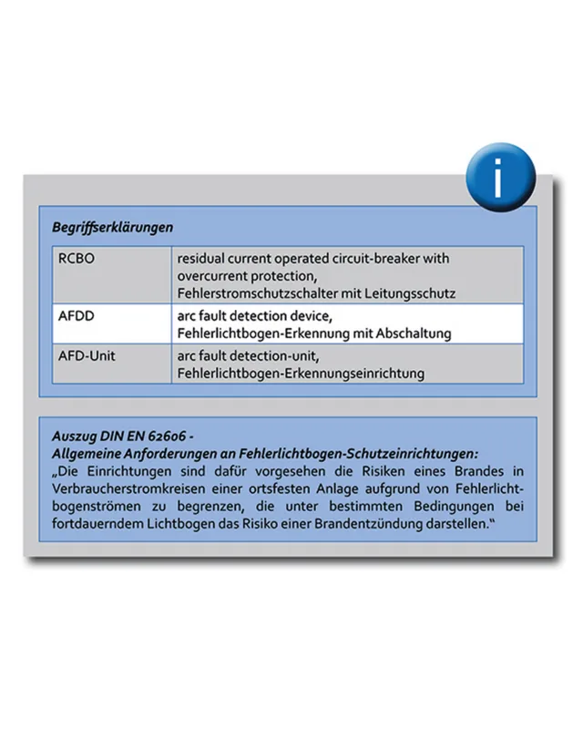
Terms
RCBO
Residual current operated Circuit-Breaker with Overcurrent
protection
AFDD Arc Fault Detection Device
AFD unit Arc Fault Detection-Unit
Function
The RCBO part of the DAFDD 1 contains a residual current circuit-breaker with
line protection for protecting persons, farm animals and material items in the event
of earth leakage currents as per VDE 0100 Part 410 and for protecting systems in the
event of a short-circuit and overload as per the requirements of VDE 0100 Part 430.
Overload tripping occurs at currents in the overload range through a short-time
delayed, heat-sensitive bimetal trip and at short-circuit currents through an electro-
magnetic instantaneous trip. The DAFDD 1 is a two-terminal device. Whereas the
RCBO functions are not voltage-dependent, the AFD unit requires a power supply
to detect arc faults. This power is supplied internally via the monitored load circuit;
as such, a separate power supply is not necessary. Arc faults are detected in the high
frequency range; a microcontroller provides evaluation.
Device form factor
RCBO residual current circuit-breaker
Type AC
Circuit-breakers with residual current characteristic AC only detect AC residual
currents. They cannot detect pulsating DC residual currents so are not permitted for
use as residual current operated protective devices in Germany. They are therefore
only available as export models.
Type A
Switches with residual current characteristic A allow the detection of sinusoidal AC
currents and pulsating DC residual currents.
Type A KV
Switches with residual current characteristic A allow the detection of sinusoidal AC
currents and pulsating DC residual currents. Because they have a response delay of
10 ms, KV design devices only respond to residual currents that last longer than a
half-period of the power frequency. In contrast to instantaneous breakers, they
          
problem-free operation, even when lightning or switching overvoltage in the system
-
ary current up to the zero point of the mains voltage. The tripping times set out in
national and international design regulations for instantaneous RCBOs are also ob-
served by the KV design devices. Therefore, in principle, these may be used instead
of a standard breaker.
Type F
Type F residual current circuit-breakers meet all requirements for type A circuit-
breakers. They also detect residual currents with mixed frequencies deviating from
50 Hz which can occur, for example, when single-phase frequency converters are
used. With an integrated response delay of 10 ms, they only respond to residual
currents that last longer than a half-period of the power frequency. As such, they
guarantee increased system availability, like switch type A KV. The tripping times
set out in national and international design regulations for instantaneous RCBOs are
observed. Therefore, in principle, these may be used instead of a standard breaker.
RCBO – line protection
B characteristic
Line protection with characteristic B ensures standard protection for lighting and

should not be used to fuse-protect load circuits with high inrush currents.
C characteristic
Miniature circuit-breakers with characteristic C are primarily suitable for power

times the rated current.
Doepke

|

|

DE EN

Chatten Sie mit Ihrem Doepke DAFDD 1 C16/0,03/2-A-Handbuch mithilfe von KI

Erhalten Sie sofortige KI-Antworten aus Ihrem Doepke DAFDD 1 C16/0,03/2-A-Handbuch

Fragen Sie alles über Doepke DAFDD 1 C16/0,03/2-A. Antworten stammen aus diesem Handbuch, mit den Seiten, auf denen sie basieren.

DAFDD 1 C16/0,03/2-A Wartungsplan

Erinnere mich, wenn eine Wartung faellig ist
Täglich (Arbeitstage)
Funktion des nicht stationären Systemschutzschalters testen

Wiederholen Sie bei nicht stationären Systemen die Funktionsprüfung, indem Sie täglich den Testknopf T drücken.

Alle 6 Monate
Funktion des Fehlerstrom-Schutzschalters testen

Drücken Sie den Testknopf T, um das Auslösen zu überprüfen. Bei stationären Systemen muss dies gemäß DGUV Vorschrift 3 mindestens alle sechs Monate erfolgen.

Kostenlose Wartungserinnerungen

Abgestimmt auf Ihr Kaufdatum. Immer kostenlos, jederzeit abbestellbar.

Mit dem Absenden stimmen Sie der Datenschutzerklarung zu. Sie konnen sich in jeder E-Mail mit einem Klick abmelden.
M: qwen/qwen3.8-flash

Stellen Sie eine Frage

0/1000

Empfehlen Sie DAFDD 1 C16/0,03/2-A?

Ja Nein

Häufig gestellte Fragen

A

Bei fest installierten Anlagen die Testtaste mindestens alle sechs Monate drücken. Bei nicht stationären oder mobilen Geräten die Prüfung täglich wiederholen, um laufende Zuverlässigkeit sicherzustellen.

Ist diese Antwort hilfreich?

A

Nein, das DAFDD 1 enthält keine wartbaren internen Komponenten. Bei Defekt muss die gesamte Einheit sofort ersetzt werden, um Sicherheitsstandards wiederherzustellen.

Ist diese Antwort hilfreich?

A

Ein gelber Blinkcode zeigt einen vom AFD-Gerät erkannten Fehler an, z. B. einen seriellen Fehler oder Dimmerproblem. Siehe die Tabelle im Handbuch für das spezifische Blinkmuster zur Diagnose des Problems.

Ist diese Antwort hilfreich?

A

Nein, die DAFDD 1-Serie ist ausschließlich für einphasige Wechselstromsysteme mit 230 Volt und 50 Hz Frequenzen konzipiert.

Ist diese Antwort hilfreich?

A

Die Garantie deckt während des Transports entstandene Schäden nicht ab. Sie gilt für Herstellungsfehler, die in professionell installierten und unveränderten Geräten innerhalb der gesetzlichen Frist gefunden werden.

Ist diese Antwort hilfreich?

A

Ja, der Neutralleiter kann auf der linken oder rechten Seite des Geräts angeschlossen werden, wodurch sichergestellt wird, dass die Installation korrekt bipolar überwacht bleibt.

Ist diese Antwort hilfreich?

M: QW-35-FL

Vorteile und Nachteile

Vorteile

  • Kombiniert RCBO- und AFD-Funktionen für zweilagigen Feuer- und Schockschutz
  • LED-Anzeigen bieten klares visuelles Feedback zum Gerätestatus und Fehlern
  • Leichte monatliche Prüfung über eingebaute Taste verlängert mechanische Zuverlässigkeit
  • Überspannungsschutz aktiviert automatisch bei 270 Volt, um Geräte zu schützen
  • Kompaktes DIN-Schienendesign passt effizient in Standard-Verteiltafeln
VS

Nachteile

  • Erfordert professionelle Installation durch qualifizierte Elektriker aufgrund von Hochspannungsrisiko
  • Bestimmte Dimmer sind möglicherweise nicht kompatibel und verursachen unnötige Auslöseereignisse
  • Gerät kann intern nicht repariert werden, was vollständigen Ersatz bei Defekten bedeutet
  • Nicht geeignet für Gleichstromnetze, was Anwendungsspektrum erheblich einschränkt
  • Überspannungsableitströme können gelegentlich weiterhin unerwünschtes Auslösen verursachen
M: QW-35-FL

Produkt Spezifikation

Typ

Hilfsschalter

Montageart

Hutschine

Rahmen

Nein

Abdeckung

Nein

M: QW-35-FL

Produkt Beschreibung

Sicherung Ihrer elektrischen Sicherheitsstandards

Die Gewährleistung der Sicherheit Ihrer Elektroinstallation ist für jeden Haus- und Gewerbebesitzer von größter Bedeutung. Moderne Anforderungen erfordern robuste Lösungen, die über den traditionellen Leistungsschutz hinausgehen. Das Handbuch des Doepke DAFDD 1 C16/0,03/2-A Lichtbogenfehler-Schutzgeräts dient als unschätzbares Mittel zum Verständnis dieser ausgefeilten Ausrüstung. Dieses Gerät integriert Funktionen eines Fehlerstromschutzschalters mit dedizierten Funktionen zur Erkennung von Lichtbogenfehlern. Durch die kontinuierliche Überwachung hochfrequenter Signale identifiziert das Gerät gefährliche elektrische Lichtbögen, bevor diese Brände auslösen. Dieser zweilagige Ansatz reduziert das Risiko in Wohn- und Geschäftsbereichen erheblich. Die ordnungsgemäße Verwendung umfasst regelmäßige Funktionsprüfungen mittels der integrierten Testtaste. Sicherheitsrichtlinien empfehlen, diese Prüfung bei fest installierten Anlagen mindestens alle sechs Monate durchzuführen. Für mobile Einrichtungen werden tägliche Prüfungen empfohlen. Das Ignorieren dieser Protokolle kann die langfristige Zuverlässigkeit gefährden. Falls das Gerät im Test nicht abschaltet, ist ein sofortiger Austausch notwendig, um ausreichende Schutzniveaus aufrechtzuerhalten. Die Installation muss strikt nach nationalen Richtlinien erfolgen. Geräte sind zur Montage auf TS 35 DIN-Schienen innerhalb von Verteilerschränken konzipiert. Verkabelungsanschlüsse erfordern Sorgfalt bezüglich Phase und Neutralleiterorientierung. Obwohl die Neutralleiterposition variabel ist, sorgt eine korrekte Ausrichtung für eine ordnungsgemäße Zweipolüberwachung. Umweltfaktoren spielen ebenfalls eine entscheidende Rolle. Die Ausrüstung sollte unter trockenen, staubarmen Bedingungen ohne aggressive Atmosphären betrieben werden. Der Schutz gegen Berührung basiert auf entsprechenden Abdeckungen, welche Sicherheitsklassenstandards erfüllen. Benutzer müssen bewusst sein, dass bestimmte elektronische Lasten wie Dimmer Fehlalarme auslösen können, wenn sie nicht vollständig mit diesem spezifischen Schutzgerätemodell kompatibel sind. Fehlersuche beinhaltet oft das Überprüfen von Lastkennlinien gegenüber Herstellerangaben. Spannungsspitzen, die 270 Volt überschreiten, aktivieren interne Sicherungsmaßnahmen, um Schäden zu verhindern. Diese Eigenschaft unterscheidet es von grundlegenden Schaltern. Technische Parameter spezifizieren die Eignung für einphasige Wechselstromsysteme mit 230 Volt Nennspannung. Gleichstromanwendungen sind ausdrücklich von zulässigen Anwendungsfällen ausgeschlossen. Wartungsanforderungen sind minimal abgesehen von periodischer Prüfung, da interne Komponenten nicht reparaturfähig sind. Defekte Einheiten erfordern einen vollständigen Austausch statt einer Reparatur. Garantieabdeckung erstreckt sich auf professionelle Installationen mit Ausnahme nicht autorisierter Änderungen. Besitzer sollten alle Dokumentationen für zukünftige Referenzen bezüglich Fehlersuche oder Konformitätsprüfungen behalten. Letztendlich verbessert die Integration dieses Schutzgeräts die gesamte Netzstabilität und priorisiert menschliche Sicherheit und Vermögenssicherung durch intelligente Detektionsmethoden.

Betriebsdiagnostik und Reparaturanweisungen

Spezifische Fehlercodes helfen Technikern, Probleme schnell zu diagnostizieren. Visuelle Anzeigen zeigen deutliche Blinkmuster an, um serielle Fehler oder interne Ausfälle zu kennzeichnen. Das Verständnis dieser Signale verhindert unnötige Panik während Störungen. Das Gerät unterstützt verschiedene Stromnennwerte, die je nach Modell zwischen zehn und vierzig Ampere reichen. Charakteristik B eignet sich für Beleuchtungskreise, während Charakteristik C höhere Einschaltströme bewältigt. Stromstoßstärke variiert über Modelle. Isolationsprüfung erfordert das Trennen von Ausgangsseiten, um Elektronikbeschädigungen zu vermeiden. Falsche Praktiken führen zu Schäden. Inbetriebnahme beinhaltet die Überprüfung von Sicherheitsmaßnahmen gemäß lokalen Vorschriften. Abschalten erfolgt nach Schaltvorgängen auf Null vor dem Reset nach Freigabe. Wenn der Schalter nicht einrastet, muss ein Elektrospezialist untersuchen. Regelmäßige Reinigung und Sichtprüfung unterstützen die langfristige Betriebintegrität ohne Spezialwerkzeuge. Herstellerangaben diktieren klare Grenzen für sicheren Betrieb in variierenden Temperaturbereichen. Lagerung muss innerhalb spezifizierter Grenzen bleiben, um Komponentenfunktion während Ausfallzeiten zu erhalten. Beziehen Sie sich immer auf die offizielle Dokumentation für detaillierte Verfahrensschritte vor Arbeitsbeginn. Nichtbeachtung von Warnhinweisen kann zu schweren Verletzungen oder Geräteausfällen führen, die teure Sanierungsbemühungen unmittelbar nach Vorfällen erfordern. Einhaltung etablierter Normen stellt maximale Effizienz und Lebensdauer für alle installierten Einheiten sicher.

M: QW-35-FL

© Copyright 2026 Manual.ly